Pneumatic Solenoid &
Servo Actuation Controller
Arduino-Based Multi-Channel Electromechanical Actuation Platform
A structured embedded control system integrating a pilot-operated pneumatic solenoid valve and dual rotary servo actuators under a unified Arduino firmware architecture — with a UART-serial dispatch interface, an enumerated actuation command taxonomy, and a completed 23-step commissioning and functional verification protocol.
System Architecture
Single-Board Multi-Channel
Actuator Control Architecture
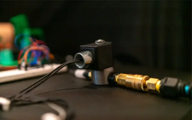
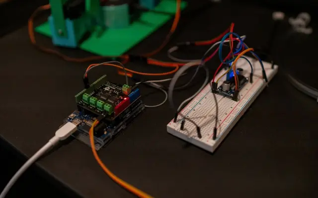
The system is built on an Arduino Uno R3 microcontroller stacked with a DFRobot Quad Motor Driver Shield v1.0 expansion module. The shield's M4 terminal block provides direct current-sourcing capability for the 12V solenoid coil, while the Arduino's digital output pins 10 and 11 generate 50 Hz pulse-width modulation (PWM) signals for rotary servo actuator position control.
- Solenoid Channel —Normally-closed (NC) fail-safe solenoid valve operating at 80 PSI nominal working pressure from a 150 PSI compressed-air reservoir equipped with a mechanical overpressure relief valve. The DFRobot shield's H-bridge output could not directly sink the solenoid coil's inductive load and inrush current, requiring the integration of an automotive-grade SPST relay (Bosch standard form factor, sourced from AutoZone) as an interposing switching element — with the shield output driving the relay coil and the relay contact switching the solenoid circuit. On de-energization, the valve fails to the closed position per its DTC (de-energize-to-close) fail-safe topology.
- Servo Channels —Two independent rotary electromechanical servo actuators driven from digital pins 10 and 11 via the Arduino
Servo.hlibrary. Power servo (pin 11) and vibe servo (pin 10) receive independent position commands with 1-second dwell at each angular endpoint. - Command Dispatch —A UART serial interface at 9600 baud exposes an enumerated ASCII command set enabling discrete actuation mode selection without firmware re-upload. Commands are dispatched via the Arduino IDE Serial Monitor or any terminal emulator capable of byte-level transmission.
Hardware Assembly
Solenoid Conductor
Termination Protocol
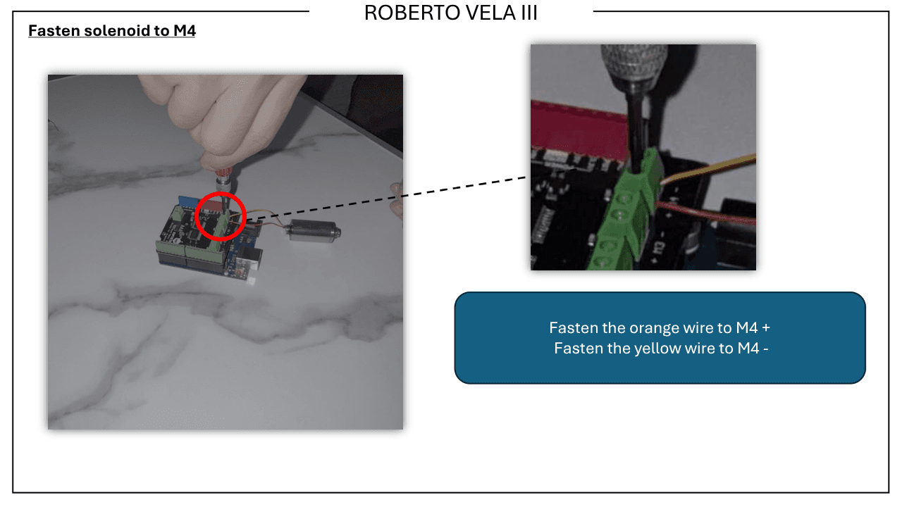
Solenoid valve conductors are prepared to a 4.5 mm strip specification per the commissioning document, then fastened to the DFRobot shield's M4 motor terminal block with a precision screwdriver — orange conductor to M4 positive, yellow to M4 negative. The terminal block provides a mechanical crimp-free conductor capture mechanism with contact resistance below 50 mΩ under rated torque.
The shield's internal H-bridge topology allows bidirectional current through the solenoid coil, enabling firmware-defined actuation polarity reversal — implemented as the forward/backward burst and direction-toggle command modes in the serial dispatch interface.
Servo Actuator Pinout Verification
PWM Output Assignment
and Continuity Check
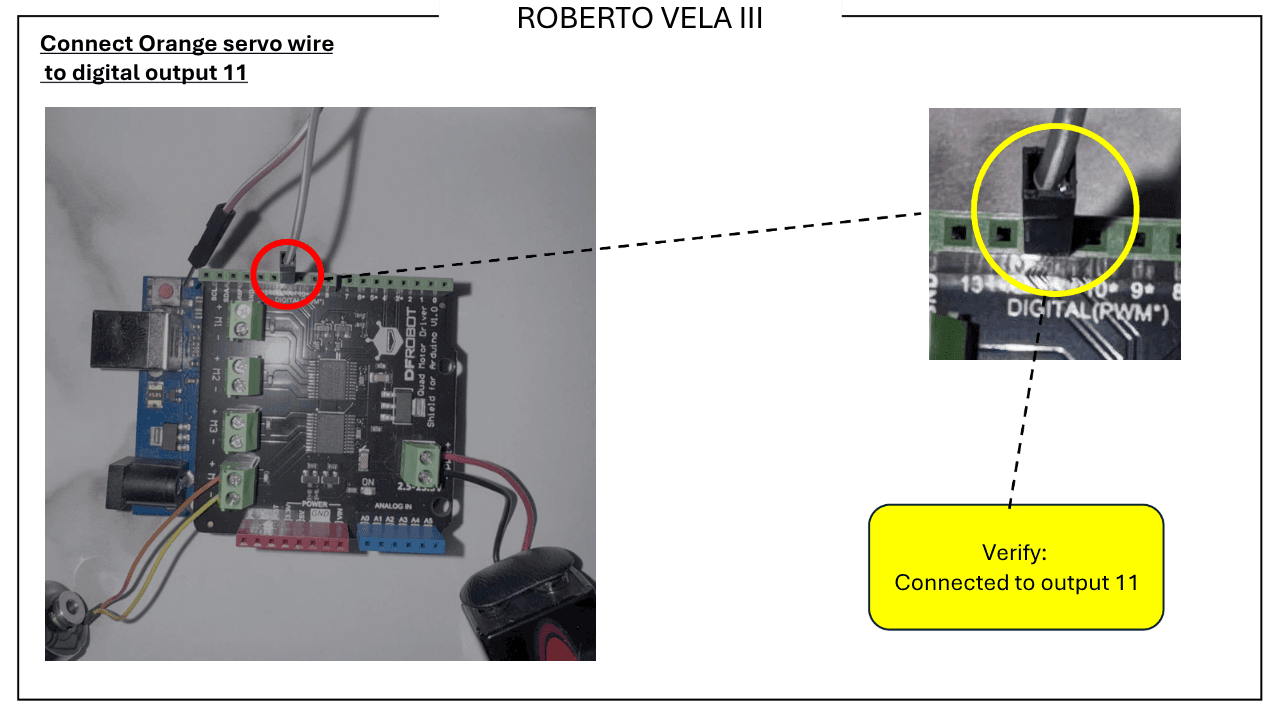
Servo actuator wiring routes from the Arduino's digital header through jumper leads to a breadboard interconnect node, isolating the servo power rail from the MCU logic supply and providing a clean mechanical strain-relief point at the breadboard tie-strip. Each servo signal conductor (orange) is verified for continuity to its assigned digital output pin prior to firmware upload.
- Power servo signal (orange) → Digital pin 11 · continuity verified
- Vibe servo signal (orange) → Digital pin 10 · continuity verified
- Servo power (white → positive, black → negative) pinout confirmed per datasheet
- Breadboard bus used as mechanical junction — no soldered joints in harness
Firmware & Serial Command Interface
Enumerated UART-Serial
Actuation Command Taxonomy
The solenoid firmware (direct_solenoid_test.ino) exposes a seven-command ASCII dispatch protocol over UART at 9600 baud. The enumerated command set enables discrete actuation mode selection — from single-pulse toggle to sustained cyclic qualification testing — without modifying or re-uploading firmware between test runs. All serial commands are acknowledged via Serial Monitor diagnostic output at startup.
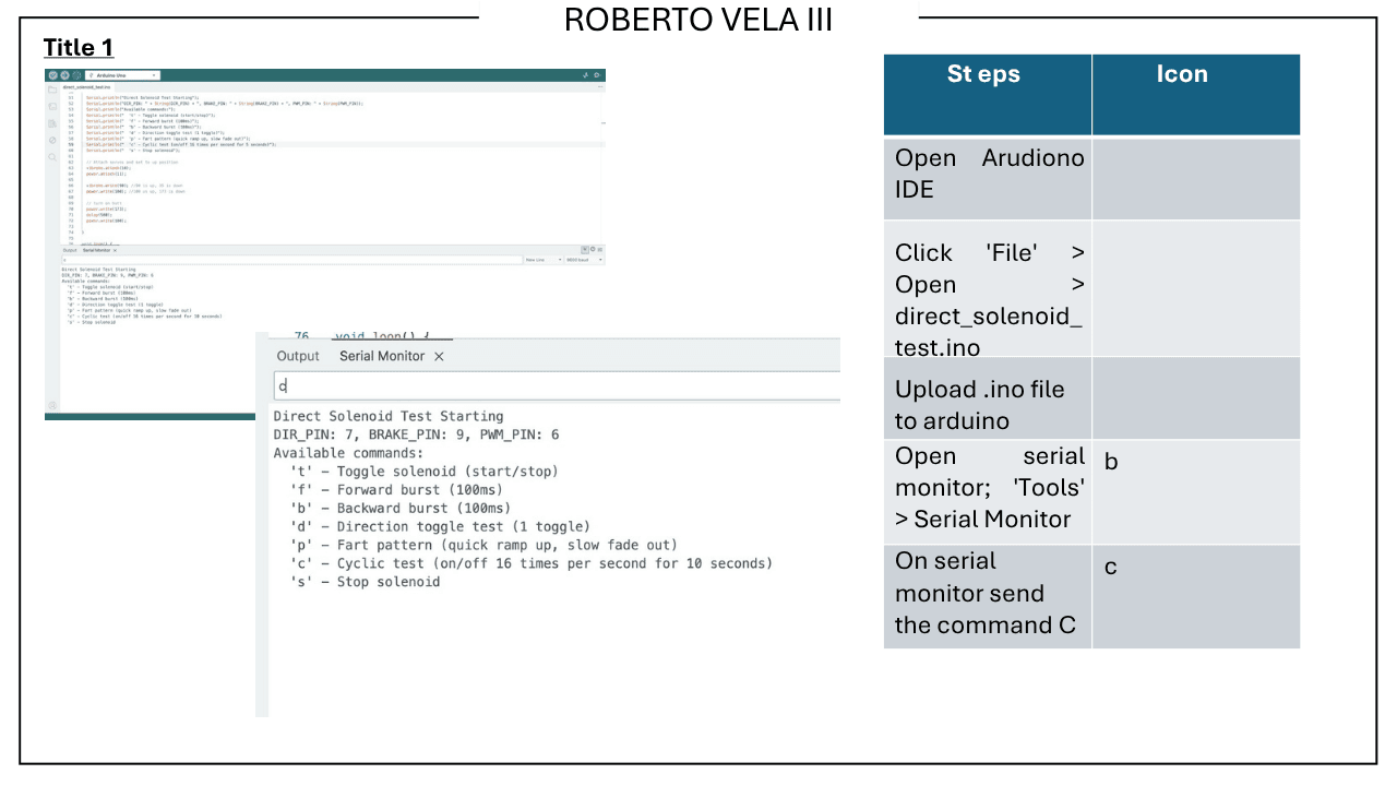
"t"
Toggle solenoid (open/close single actuation)
"f"
Forward burst — 100 ms energization pulse
"b"
Backward burst — 100 ms de-energization pulse
"d"
Direction toggle — alternates actuation polarity
"p"
Pattern sequence — rapid ramp-up, slow fade-out
"c"
Cyclic test — 16 Hz toggle for 10 s continuous
"s"
Stop — de-energize all channels immediately
Firmware PIN configuration: DIR_PIN 7 · BRAKE_PIN 9 · PWM_PIN 6. All channel states de-energize on stop command.
Functional Verification Checkout
Servo Range-of-Motion
Qualification Protocol
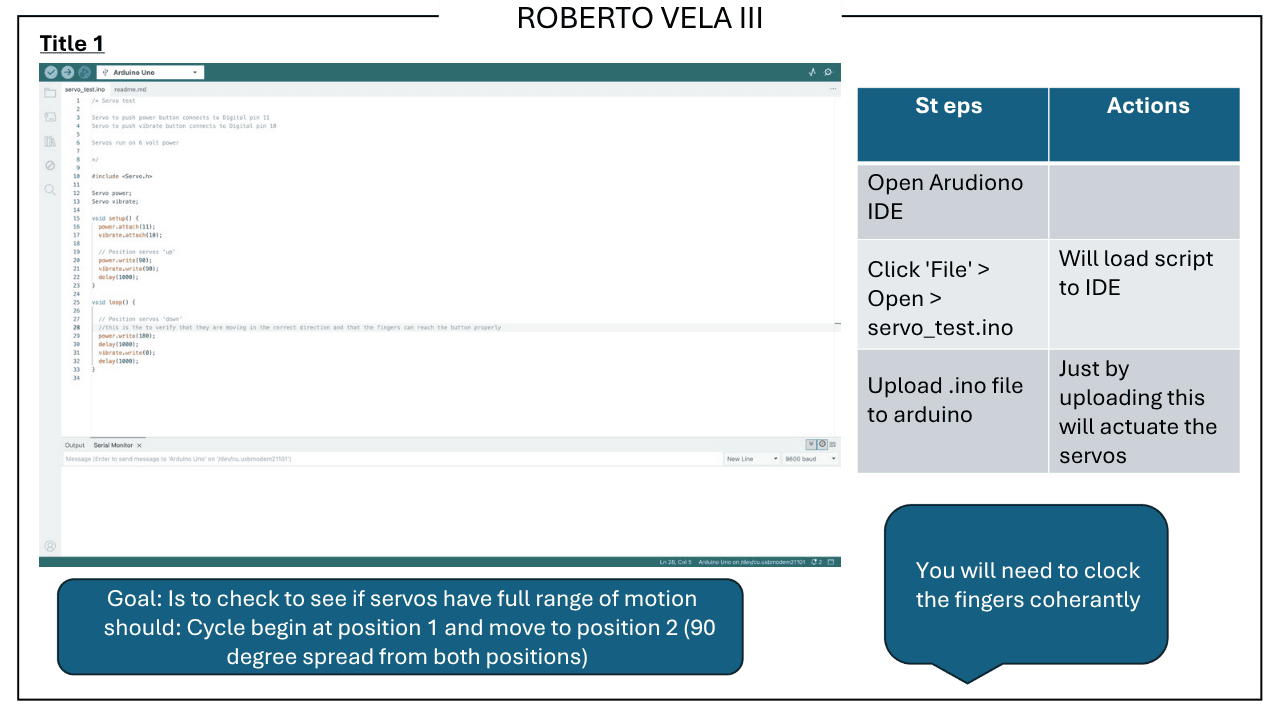
The servo functional checkout script (servo_test.ino) performs a continuous position-cycling sequence from 0° to 90° — validating the full angular displacement envelope of both actuators prior to operational integration. The test confirms coherent finger-timing across both servo channels, ensuring synchronized mechanical actuation under firmware control.
- Upload
servo_test.inoto trigger autonomous position cycling - Servo positions cycle: 100° (up) → 180° (down) · 1 s dwell per position
- Full angular displacement envelope verified on both power and vibe channels
- Checkout passes when both servos execute coherent, synchronized sweep
- Solenoid quality check performed separately via serial dispatch command
Hazard Operability Analysis (HAZOP)
Operating at 150 PSI supply / 80 PSI working pressure with an inductive solenoid load elevated the consequence severity of unintended actuation events. HAZOP identified three hazard scenarios: (1) H-bridge PWM pin assertion during a firmware hang state holding the relay coil energized; (2) uncontrolled pressure release on valve actuation without downstream flow control; (3) tank over-pressurization. Controls implemented: firmware-level forced de-energization on stop command "s" driving relay coil to open state; NC fail-safe valve topology ensuring closure on power loss; mechanical overpressure relief valve on the compressed-air reservoir providing independent pressure-limiting protection independent of firmware state.
System Specifications
Microcontroller
Arduino Uno R3 · ATmega328P · 16 MHz · 32 KB Flash · 2 KB SRAM
Motor Driver Module
DFRobot Quad Motor Driver Shield v1.0 · M4 terminal block · 12V/2A per channel
Solenoid Interposing Switch
Automotive-grade SPST relay (Bosch standard form factor, AutoZone) · Shield H-bridge output drives relay coil · relay contact switches solenoid circuit
Pneumatic Actuator
Normally-closed (NC) fail-safe solenoid valve · de-energize-to-close topology · 4.5 mm conductor termination
System Supply Pressure
150 PSI regulated supply · compressed-air reservoir with mechanical overpressure relief valve
Nominal Operating Pressure
80 PSI working pressure at valve inlet
Fail-Safe Valve Behavior
De-energize-to-close (DTC) — valve returns to closed position on power loss or firmware stop command
Servo Actuators
Dual rotary servo actuators — power servo (pin 11) · vibe servo (pin 10)
PWM Signal Output
Digital pins 10 & 11 — 50 Hz PWM, 1–2 ms pulse-width envelope
Power Architecture
9V alkaline electrochemical cell → DFRobot shield VIN · Arduino via USB
Command Interface
UART serial dispatch · 9600 baud · enumerated ASCII command set
Solenoid Actuation Modes
Toggle · Forward burst (100 ms) · Backward burst (100 ms) · Cyclic test (16 Hz / 10 s) · Stop
Servo Angular Displacement
0° → 90° full-range sweep · ~1 s transition dwell at each position
Solenoid Wiring Spec
Orange → M4+ · Yellow → M4− · 4.5 mm conductor strip length
Commissioning Protocol
Step-indexed annotated photo documentation · 23-step assembly and verification sequence
Functional Checkout Status
Verified complete — solenoid quality check + servo range-of-motion validation